BTSTC-INS0140
Share to:
Category:
Keywords:
BTSTC-INS0140
Details
Overview
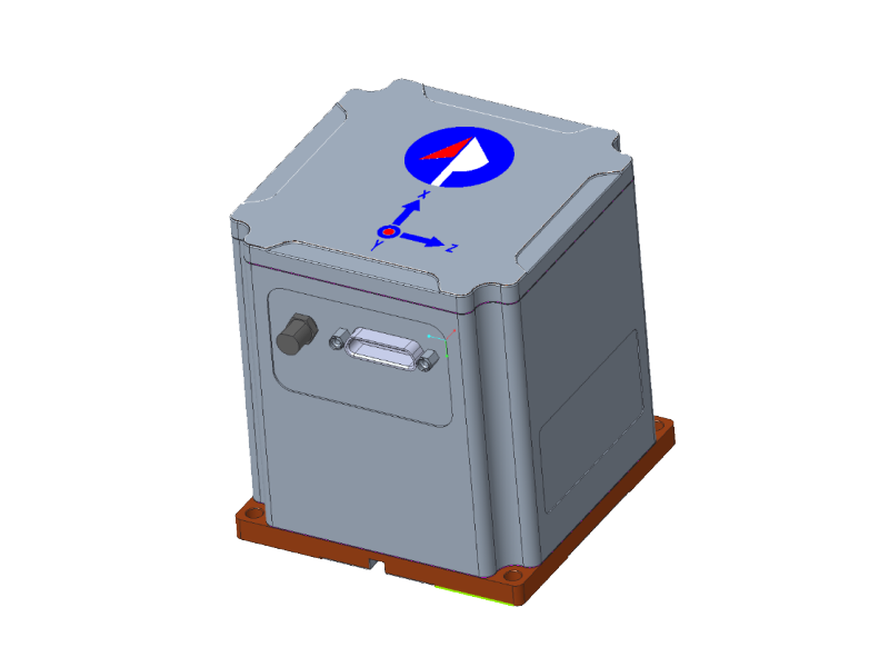
BTSTC-INS0140 inertial navigation system uses fiber optic gyroscope and quartz flexible accelerometer as inertial sensing devices, and integrates navigation computer, I/F conversion, DC power supply, satellite receiver and other supporting circuits.
It provides high-precision position, speed, heading, pitch, roll and other attitude reference information for airborne platforms, and to output carrier acceleration, angular velocity and position change information.
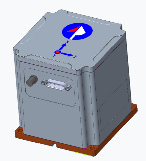
Fig. 1 BTSTC-INS0140 Inertial Navigation System
Technical specification
Table 1 Main technical parameters
| Item | Unit | Indicators | |
| Align | Heading (single antenna, static, 1 σ) | ° | <0.8 |
| Horizontal attitude (pitch angle, roll angle, 1σ) | ° | <0.03 | |
| GNSS/INS Integrated navigation accuracy | Horizontal position (single point positioning, 1 σ) | m | <1.5 |
| Velocity, 1σ | m/s | <0.1 | |
| Heading (single antenna, dynamic post-convergence, 1σ) | ° | <0.2 | |
| Horizontal attitude (pitch angle, roll angle, 1σ) | ° | <0.03 | |
| Pure inertial Navigation accuracy | Position, pure inertia 5min, CEP | m | <300 |
| Position, pure inertia 60 min, CEP | nmile | <6 | |
| Heading, pure inertia 60 min | ° | <0.2 | |
| Horizontal attitude, pure inertia 60 min | ° | <0.1 | |
| IMU Metrics | Gyro bias stability | °/h | <0.3 |
| Random walk coefficient | °/ | <0.03 | |
| Maximum range of angular velocity measurement | ° | >400 | |
| Bias stability of accelerometer | ug | <60 | |
| Acceleration measurement range | g | ±30 | |
| Communication interface | RS422/485/232 configurable intelligent communication port
9600bps~921600bps | Route 3 | |
| RS232 monitoring communication port | Route 1 | ||
| GNSS data link communication port | Route 1 | ||
| Data update rate | Hz | Default 200 | |
| INS solves the frequency | Hz | >200 | |
| GNSS update frequency | Hz | 5 | |
| Electrical interface | Supply voltage | V | 9~36 |
| Power consumption | W | <20 | |
| RF antenna output | 100mA@5V | ||
| Mechanical interface | Dimensions (excl. connectors) | mm | 80 × 80 × 88 |
| Weight | g | <950 | |
| Data interface | J30J-25ZK | ||
| RF interface | SMA | ||
| Environmental adaptability | Operating temperature | ℃ | -40~60 |
| Storage temperature | ℃ | -45~70 | |
| Waterproof standard | MIL-STD-810F, 506.4 | ||
| Vibration environment | GJB151 A Propeller Aircraft Platform | ||
| Impact conditions | 25 g, 11ms, half sine wave | ||
| MTBF | h | >7000 | |
Table 2 Technical parameters of three-axis integrated FOG
| No. | Item | Unit | Indicators |
| 1 | Preparation time | s | ≤2 |
| 2 | Zero-bias stability (room temperature, 10 s smoothing, 1σ) | (ο)/h | ≤0.3(1σ) |
| 3 | Zero-bias stability (variable temperature, 10 s smoothing, 1σ) | (ο)/h | ≤0.6(1σ) |
| 4 | Zero-bias repeatability (1σ) | (ο)/h | ≤0.3 |
| 5 | Random walk coefficient | (ο)/√h | ≤0.03 |
| 6 | Scale factor nonlinearity | ppm | ≤50 |
| 7 | Gyroscope measuring range | (ο)/s | ±500 |
Table 3 Technical parameters of Quartz Flexible Accelerometer
| No. | Item | Unit | Technical indicators |
| 1 | Enter the range | g | >60 |
| 2 | Bias | mg | ≤20 |
| 3 | Offset monthly stability (1σ) | μg | <60 |
| 4 | Bias Temperature Coefficient | μg/℃ | <30 |
| 5 | Monthly stability of scale factor (1σ) | ppm | <100 |
| 6 | Scale factor temperature coefficient | ppm/℃ | <30 |
| 7 | Operating temperature range | ℃ | -45~+80 |
| 8 | Threshold | μg | <5 |
| 9 | Impact | g,ms | 120g,4.5ms,1/2sin |
| 10 | Vibration | g,Hz | 8grms(20~2000)Hz |
Table 4 Technical Specifications of Receiver
| Frequency point | BDS B1/B2/B3 GPS L1/L2 GLONASS L1/L2 Galileo E1/E5b |
| Initialization time | < 5 seconds (typical) |
| Single Point Positioning (RMS) | Plane: 1.5m Elevation: 3.0 m |
| Data update rate | 5Hz |
| Time accuracy (RMS) | 20ns |
| Velocity Accuracy (RMS) | 0.03m/s |
Table 5 I/F Conversion Circuit Index
| No. | Content | Unit | Indicators |
| 1 | Number of conversion channels | —— | 3 |
| 2 | Current measurement range | mA | up to ± 80 (Customizable) |
| 3 | Full-scale output frequency | kHz | 512 |
| 4 | Zero bias | nA | ±200 |
| 5 | Zero-bias temperature coefficient | nA/℃ | < |
| 6 | Scale factor non-linearity | —— | <5×10⁻⁵ |
| 7 | Small signal deviation | pulse/s | 1 |
| 8 | I/F Scale Factor Temperature Coefficient | ppm/℃ | 15 |
Structural dimensions(mm)
Overall dimension: 80 ± 0.1 × 80 ± 0.1 × 88 ± 0.1,
Weight: less than 950 g,
Installation dimension: (mm) 72 ± 0.1 × 72 ± 0.1 (L × W),
hole position: Φ4.2 × 4,
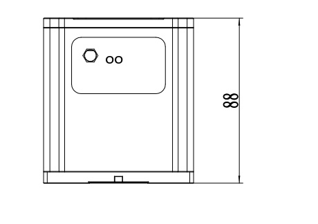
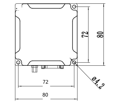
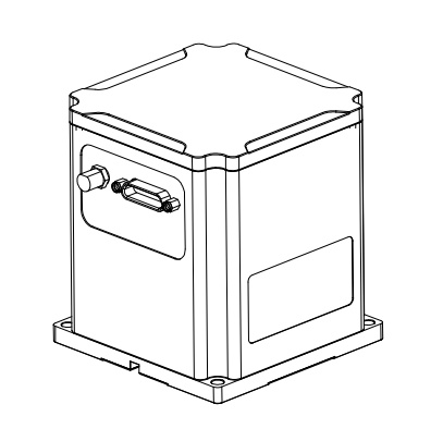
Fig. 2 Structural dimension of BTSTC-INS0140 INS
Electrical interface
1. Power supply
The navigation system is powered by a DC power supply with a wide DC voltage of 9V ~ 36V and a nominal power supply voltage of 24V. The steady-state power consumption is less than 20W, the transient power consumption is less than 50 W, and the transient width is less than 1 ms.
Table 6 Power Supply Requirements
| No. | Name | Request |
| 1 | Voltage range | +9V~+36V |
| 2 | Power ripple (Vpp) | 20mV |
| 3 | Supply power | >50W |
2. Definition of connector and core point
1 LF connector and 1 SMA RF connector are used for the external data power connection of the navigation system, as shown in the figure below.
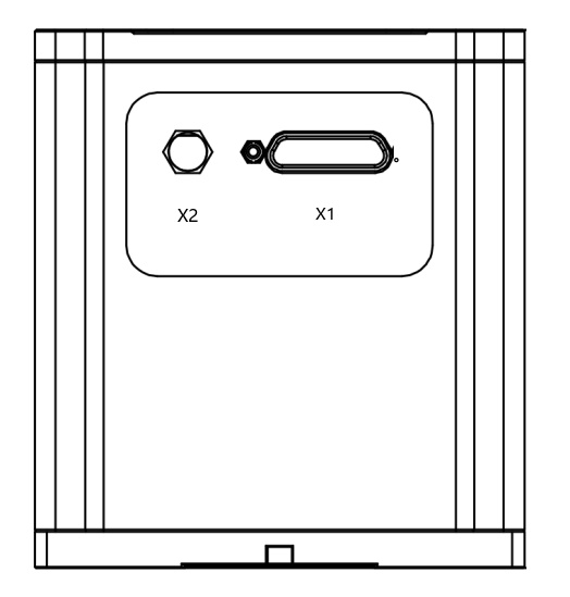
Fig. 3 BTSTC-INS0140 Connector
- The low-frequency connector is X1, which is J30J rectangular aviation connector.
- X2 is a high-frequency connector, which is connected to the GNSS positioning antenna and adopts the SMA female socket.
Table 7 Definition of Core Point
| No. | Content | Remark |
| 1 | 24V input | |
| 2 | 24V GND | |
| 3 | JKTxD Monitor 232 Send | |
| 4 | DGND Digital Ground | |
| 5 | JKRxD Monitor 232 Receive | |
| 6 | DGND Digital Ground | Flight control communication serial port |
| 7 | COM0Ty + 422 Send + | |
| 8 | COM0Ry + 422 receive +/232 receive | Flight control communication serial port |
| 9 | COM0Ty-422 Send-/232 Send | Flight control communication serial port |
| 10 | COM0Ry-COM0422 Receive- | |
| 11 | GPSTxD GPS 232 Send | |
| 12 | GPSRxD GPS 232 Receive | |
| 13 | GPS 1PPS output 3.3 V | |
| 14 | DGND Digital Ground | |
| 15 | AIO _ OUT A-channel I/O output | |
| 16 | PPS1 TTL 3.3/5V IN | Anti-jamming module input |
| 17 | COM2Ty-422 Send- | Anti-jamming module input |
| 18 | COM2Ry-422 Receive- | Anti-jamming module input |
| 19 | COM2Ty + 422 Send + | Anti-jamming module input |
| 20 | COM2Ry + 422 Receive + | Anti-jamming module input |
| 21 | COM1Ty + 422 Send + | |
| 22 | COM1Ry + 422 receive +/232 receive | |
| 23 | COM1Ty-422 Send-/232 Send | |
| 24 | COM1Ry-422 receive- | |
| 25 | DGND Digital Ground/GND _ 2 |
Table 8 Electrical Signal Characteristics
| Item | Unit | Minimal | Typical | Max |
| 25 ℃ steady state power consumption | W | 18 | 30 | |
| Startup power consumption -40℃~60℃ | W | 40 | 50 | |
| Data valid time | s | 2 | 3 | |
| RS422 baud rate error | % | 0.1 | ||
| RS422 input impedance | Ω | 120 |
Communication protocol
The communication protocol is optional. The default configuration of the communication serial port in this system is COM0 RS232 to output STD8B protocol. At the same time, it receives the correction information from the flight control to the inertial navigation. The baud rate is the start bit of the 460800,1 bit, 8 data bits, and 1stop bit. There is no parity check.
Table 9 Format of STD8B message (from inertial navigation to flight control)
| No. | Format | Content | Unit | Description |
| 1 | UINT8 | 0xEB | — | Frame header |
| 2 | UINT8 | 0x90 | — | Frame header |
| 3 | UINT8 | —— | — | Frame length N, total number of data bytes from frame header to checksum |
| 4 | UINT8 | 0xD1 | — | Frame ID |
| 5 | UINT32 | —— | — | Frame count |
| 6 | UINT8 | —— | — | Status |
| 7 | float | —— | rad | Pitch Angle |
| 8 | float | —— | rad | Roll Angle |
| 9 | float | —— | rad | Heading angle |
| 10 | float | —— | ° | Flight Path Angle |
| 11 | float | —— | rad/s | Pitch rate |
| 12 | float | —— | rad/s | Roll rate |
| 13 | float | —— | rad/s | Heading angular rate |
| 14 | INT32 | —— | 10(-7)° | Longitude |
| 15 | INT32 | —— | 10(-7)° | Latitude |
| 16 | INT32 | —— | 0.01m | High air pressure |
| 17 | INT32 | —— | 0.01m | GPS high |
| 18 | INT32 | —— | 0.01m | Filter high |
| 19 | float | —— | m/s | Northbound speed |
| 20 | float | —— | m/s | Eastbound speed |
| 21 | float | —— | m/s | Earthward velocity |
| 22 | float | —— | m/s | Airspeed |
| 23 | float | —— | m/s2 | Northward acceleration |
| 24 | float | —— | m/s2 | Eastward acceleration |
| 25 | float | —— | m/s2 | Ground acceleration |
| 26 | UINT8 | —— | — | Number of satellites |
| 27 | UINT16 | —— | 0.01m | Horizontal precision factor |
| 28 | UINT16 | —— | 0.01m | Vertical precision factor |
| 29 | UINT8 | —— | — | GPS status |
| 30 | UINT8 | —— | h | GPS time |
| 31 | UINT8 | —— | m | GPS minutes |
| 32 | UINT8 | —— | s | GPS seconds |
| 33 | INT8 | —— | ℃ | Temperature |
| 34 | INT16 | —— | ° | Dual antenna heading |
| 35 | INT16 | —— | ° | Standard deviation of course |
| 36 | UINT8 | —— | — | Sensor status |
| 37 | UINT8 | —— | 100ms | Internal GPS sampling interval |
| 28 | UINT8 | —— | 100ms | External GPS sampling interval |
| 39 | float | —— | m/s | GPS northbound velocity |
| 40 | float | —— | m/s | GPS eastbound velocity |
| 41 | float | —— | m/s | GPS ground speed |
| 42 | UINT16 | —— | — | Milliseconds in GPS seconds |
| 43 | UINT8 | —— | — | GPS days within a week |
| 44 | UINT16 | —— | — | GPS Week |
| 45 | UINT8 | —— | — | AHRS status |
| 46 | float | —— | rad | Pitch Angle |
| 47 | float | —— | rad | Roll Angle |
| 48 | float | —— | rad | Heading angle |
| 49 | UINT8 | —— | — | Checksum low byte |
| 50 | UINT8 | —— | — | Checksum high byte |
Table 10 Correction information (from flight control to inertial navigation)
| Byte | Definition | Explain | Data type |
| 0-1 | Frame header | 0x90EB | |
| 2 | Length | 0x18 | |
| 3 | ID | 0xA2 | |
| 4-7 | Frame count | U32 | |
| 8 | Status | Bit 0: airspeed status Bit2: barometer status 1: Fault 0: OK | U8 |
| 9-12 | Barometric pressure and high altitude | Unit: 0.01 m | S32 |
| 13-16 | Airspeed | Unit: 0.1m/s | S32 |
| 17 | Command word | 0 x00: None 0 X11: group 0 x22: pure habit 0X33: Atmospheric combination enabled 0 x44: Atmosphere combination off | U8 |
| 18 | Reserve 1 | U8 | |
| 19 | Reserved 2 | U8 | |
| 20 | Reserved 3 | U8 | |
| 21 | Reserved 4 | U8 | |
| 22-23 | Checksum |
Reliability
Table 11 Reliability Prediction of Components of Inertial Navigation System
| No. | Object | λ i failure rate (10 -6 /H) |
| 1 | Accelerometers (3) | 39.97 |
| 2 | Fiber-optic gyroscope | 41.44 |
| 3 | DC power supply | 16.31 |
| 4 | Navigation computer | 15.21 |
| 5 | Electrical system | 1.285 |
| 6 | GNSS board | 21.91 |
| System | Work failure rate | 136.1250 |
| MTBF | 7346.19h |
Prev
Next
Inquiry
Please leave your E-mail and our professionals will contact you as soon as possible!


