

BTSTC-SIM200
Share to:
Category:
Keywords:

BTSTC-SIM200
Details
Overview
BTSTC-SIM200 satellite signal simulator is a multi-system satellite navigation signal generator which can support GPS-L1, GLONASS L1, BDS-B1I, BDS-B2 and BDS-B3I.
Users can simulate and generate ideal satellite signals received by navigation receivers in different environments by setting parameters.
At the same time, it can also conduct wired or wireless (During wireless test, the satellite signal simulator shall be equipped with a transmitting antenna) performance test on the satellite receiver under the condition that the satellite signal cannot be received (Such as in the plant and cavern).
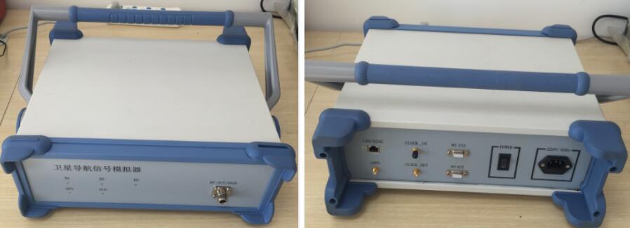
BTSTC-SIM200 Satellite Signal Simulator
Features & Key Performance
Features
• It can simulate the satellite navigation signal received by the receiver under high dynamic and static conditions.
• Users can select the satellites in the five navigation systems for any combination and collocation.
• GPS L1 is designed with 16 channels, which can simulate 16 GPS satellite navigation signals at the same time.
• GLONASS L1 is designed with 16 channels, which can simulate 16 GLONASS satellite navigation signals at the same time.
• BDS B1I (Incl. Beidou II and Beidou III satellite signals) is designed with 32 channels, which can simulate up to 32 Beidou B1I satellite navigation signals at the same time.
• BDS B2 is designed with 16 channels, which can simulate 16 Beidou B2 satellite navigation signals at the same time.
• BDS B3I (Including Beidou II and Beidou III satellite signals) is designed with 32 channels, which can simulate up to 32 Beidou B3I satellite navigation signals at the same time.
• With the signal generation channel gating function, the user can select to use a specific channel for generating navigation signals, and can also individually set the strength of the signal generated by each signal channel.
• With the navigation signal attenuation control function, the user can separately set the attenuation amount of the five satellite navigation analog signals finally output.
• It has the function of setting the motion trajectory of the receiver. User can set the motion trajectory and load the typical motion trajectory through the upper computer of the simulator, so as to facilitate the use of the test user.
• The simulator has the real-time status display function, which displays the type, quantity, number, elevation angle, pseudo-range, health status and other information of the satellite currently being simulated to the user, and displays the sky view of the current online satellite and the motion trajectory view of the receiver to the user.
• With RF cable interface and repeater antenna interface, users can choose to use wireless mode or wired mode to receive satellite analog signals.
Output Frequency
| GPS L1 | 1575.42MHz |
| GLONASS L1 | 1602MHz ±10MHz |
| BDS B1 | 1561.098MHz ±2.046MHz |
| BDS B2 | 1207.140MHz ±2.046MHz |
| BDS B3 | 1268.52MHz ±10.23MHz |
Signal Dynamic Range
Maximum Speed: ± 15km/s
Maximum Acceleration: ± 1000m/s2
Maximum Jerk: ± 1000m/s3
Signal accuracy
Pseudorange phase accuracy: ≤ 0.05m
Pseudorange change rate accuracy: ≤ 0.005m/s
Inter-channel consistency: ≤ 0.1m (code), ≤ 0.005m (carrier)
Orthogonality of carrier phase modulation of I and Q branches: ≤ 3 ° (1)
Signal quality
Harmonic power: ≤ -40dB
Carrier suppression: ≥ 40dB
Frequency stability: ≤ 2.0 × 10 -10 /day
Signal output power
RF output range: -130 ~ -70dBm
Control range: 0 ~ 60dB
Minimum adjustable resolution: 1dB
Simulator interface
Power input: AC 220V, 50Hz
Communication interface with upper computer: 2 RS232, Ethernet 10/100Mbps
Transmitting signal output port: 2 (N-KF5)
1PPS output port: 2
Indicators: power indicator and satellite operation status indicator
Physical parameters
Dimension: 200 × 150 × 80mm
Weight: ≤ 5 kg
Recommended Application
► Verify the satellite receiver algorithm in the development stage, such as dynamic performance, navigation algorithm and satellite condition complex scene simulation.
► Conduct wired or wireless performance test on the satellite receiver under the condition that the satellite signal cannot be received (Such as in the plant and cavern).
► Test the receiving sensitivity of the satellite receiver after the RF output signal of the simulator is calibrate.

Inquiry
Please leave your E-mail and our professionals will contact you as soon as possible!


Copyright © Beijing Telecompass Space Technology Co., Ltd. Powered by 300.cn TAG Privacy Policy